It’s a kit

by Chuck April 22, 2013

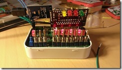
WP_20130420_003One of the guys on the COSMAC ELF mailing list, Bill Rowe, asked the people on the list if they would be interested in purchasing a run of boards for my serial port adapter. Right after I read that on the mailing list, I saw a message from Bill in my inbox asking me if I’d be interested in working with him to make a printed circuit board for the project and sell it to people who are interested.

I was OK with the idea, but with everything that’s going on with Dana I haven’t had a lot of time for other projects. Or at least I didn’t think that I did. I sent the schematic and board files to Bill so that he could make a first pass on them – once he sent them back I started playing with the board files until I had something that I could send off to Osh Park to have fabbed. Waiting the two weeks that it takes to get the boards back isn’t fun, but it beats waiting months – or not making the project at all because you don’t have a board.

Anyway, the boards came back from Osh Park, the parts that I ordered online came in (along with a whole bunch of other stuff that I didn’t really need but I thought, what the heck, I’m ordering) and I started finding all of the little things that I managed to do wrong. The DB-25 connector needs to be on the solder side of the board, not the component side. Somehow I missed where I crossed two traces. After I corrected those two faults (one with a knife and a bit of wire, the other by putting the LEDs on the solder side)  it actually worked the first time when I got the prototype built.

I’m pretty proud of the whole thing. Something that I designed and outsourced work on and built myself all works like I intended it to.

I’ve already sent out the Rev. B of the board. It will have the DB-25 connector on the other side, and with that change I was able to add a couple of other jumpers to make it easier to put the LED enable and oscillator enable lines under control of the Picaxe. But the first one will always have a special place, ‘cause it was my first.

Tags:

Electronics

Terrible transistors

by Chuck February 14, 2013

D-Latch-ResetThat picture represents a terrible, terrible idea. Bad. Awful. Nasty. But one that is oh, so tempting. After the Visual 6502 Web site posted the control logic for the 1802, there has been a certain amount of wishful sort of thinking going around on the COSMAC ELF mailing list – along the lines of “I wonder how hard it would be to build an 1802 out of discrete transistors.” I’ll admit it. It crossed my mind. I’ve been working on building the 1802 control logic in Logic Circuit (see my last post) but I started wondering what it would take to build the logic gates that I’m simulating out of transistors.

So I did a little searching on the Web to find out how to build a 2-input NAND gate out of transistors. Turns out that it’s incredibly easy to find that information. And once you’ve found it, it’s pretty darn easy to build one on a breadboard. Or four, ‘cause that’s what you need to build a D-type transparent latch. That’s what you see there on the breadboard. Each of the little groups is a NAND gate, three 2-input NANDs and one 3-input NAND. In the section of the control logic that I’ve modeled there are 10 transparent latches of various orientations. The number of transistors goes up pretty darn fast in this thing.

Tags:

Electronics

Simulating the RCA 1802 control logic

by Chuck February 13, 2013

I've started building out the 1802 control logic from http://visual6502.org/wiki/images/6/64/Rca1802-control-reversed.gif using Logic Circuit (http://www.logiccircuit.org/). There have been a couple of things that I've had to kinda take on faith, but I seem to be getting some results.
 
I've been trying to create modules out of related gates, so far I've been able to get three modules working:

  • The Reset/Load/Wait/Run logic (U8-U11 and U73 to 78). I had to reverse the value on the CLR line to get it to work, so there may be an issue in the original tracing, but once I put an extra inverter in the CLR line the logic in that section worked great. There are only three signals that come out of this section, /LOAD, /RESET, and the clock.
  • The Johnson counter that drives the operation sequence (U133 to 139 and U190 to 193). This section has two inputs, the clock and the /RESET line. There are 7 outputs from this section, SEQ0 to SEQ7. I created special versions of D-type transparent latches that match layout of the latches in the schematic to make it easier to lay out the latches. This is an interesting section of the control logic to watch run. I attached "LEDs" to the sequence outputs so that I could follow the sequence visually. I expected each LED to light up in turn, but what happened was different. SEQ0 goes high on the rising edge of CLK0, SEQ1 goes high on the falling edge of CLK0. CLK1 raises SEQ2 and SEQ3, etc. until all of the SEQ outputs are high at the falling edge of CLK3. On the rising edge of CLK4 SEQ0 goes low, followed by SEQ1 on the falling edge of CLK4, and so on until SEQ7 goes low on the falling edge of CLK7.
  • The two 3-to-8 line decoders and the enable logic (U1 to U4). I combined these 4 chips into a single module that has 5 inputs (enable, B7 to B4) and 16 outputs (i0x to iFx). I set up the module so that the 16 outputs were in the order that the appear from top to bottom in the schematic to make it easier to follow the logic.

I zipped up the Logic Circuit data file that I've been working on and put it on my Web site. You can download the file from http://www.bramblyhill.com/downloads/RCA1802-control.zip. If you download the zip file, you'll need to install the latest version of Logic Circuit from the Web site above. It does require the .NET Framework 4.0 or higher -- if you're running Windows 7 or 8 you have that installed. If you're running Windows Vista or NT you can install the Framework from Microsoft's Web site (http://www.microsoft.com/en-us/download/confirmation.aspx?id=17851) if you haven't already.

Tags:

Electronics

Log in